Wiring Diagrams, Brochures, Cut Sheets, Design Guides, and Other PDFs
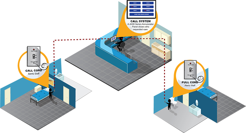
- Visual Call System – Brochure
- Annunciator Panel – Easy Label 1-48 Zones - A-4448-1
- Annunciate Panels with LED indicators – 10-225 Zones - A-4XXX
- Annunciator Station 3 & 6 Zone - A-40003A - A-4006A
- Bedside Station B-111 - B-113 - B-122
- Bedside Station B0111EP w 20 Pin Connector
- Call Cords Oxygen Env - 6 or 10ft - SW-206 - 210 - SW-406A - 410A
- Call for Aid – Small 1-2 Zone Visual Systems Bed - Bath or Button
- Call Stations in optional white color
- Check in Station, Push Button - E-107
- Control Module w Triple Status
- Corridor Lights 1, 2, or 3 LED Bulbs
- Corridor Lights L-101A - L-201A - L-301A
- Corridor Lights LS-101AS Steady LS-201AP Pulsing
- Corridor Lights Optional Decorative Cover - Alabaster Glass - LF-100
- Duty Station - DS-110
- Flasher Module, P-5000F
- Power Supply 1AMP - 12 or 24 VDC - P-512241A
- Power Supply 3AMP - 12 or 24 VDC - P-512243A
- Power Supply w Battery Backup 4AMP - 12 or 24 VDC - B-5243A
- Pull Cord (Cord Only) w Optional for Pull Cord Station Sanipull - SP-ST
- Pull Cord Station w Momentary Switch, E-144
- Pull Cord Station w Dual Status - E-104 - E-104-1WP
- Pull Cord Station w Single Status - E-114 Series
- Pull Cord Station w AntiMicrobial Glow in the Dark Cord
- Push Button Panic Station - P-116
- Push Button Panic Station w flush button - P-120
- Push Button Station - E-101 - 103 - 113
- Push Button Emergency Station - DE108C Rev 210617
- Push Button Emergency Station Code Blue - DE108CD Rev 210617
- Staff Stations - S-111 - S-112
- Toggle Switch Station - E-105
- Visual Call System – Components for Single, Dual or Triple Status Systems
- Visual Call System – Single Status Operations and Specifications
- Visual Call System – Dual Status Operations and Specifications
- Zone Light w Triple Status - Z-103
Visual Nurse Call Wiring Diagrams
- Annunciator A-4006A Wiring - Drawing 90010-11
- Check-In Station E-107 Single Status Wiring - Drawing 90078-08
- Flasher Module P-5000F Wiring - Drawing 90085-12
- Pull Cord Station E-114-3 Single Status Wiring - Drawing 90014-06
- Single Status Latching System Wiring A-4006L - Drawing 90037-06
- Single Status System Wiring - Drawing 90003-13
- Smoke Detector SD-4000 Triple Status Wiring - Drawing 90017-16
- Zone Light Z-103 Wiring - Drawing 90008-08
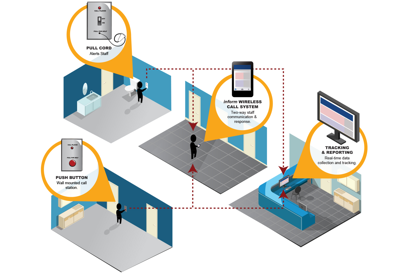
- inform Mobile Nurse Call System Overview Brochure
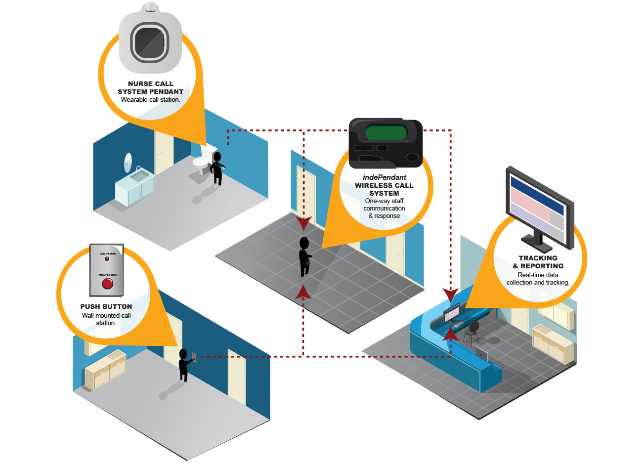
- IndePendant Wireless Call System Overview Brochure
- inform I A Mobile Nurse Call App Brochure
Component Brochures
- Alphanumeric Pager PP-9000-AW2 - PP-9000-AW5
- Area Control Gateway RC6080 - DRC6080C
- Call Cord Standard, 6 or 10 ft. SW-106
- Receiver 4 or 16-Channel RC-204DE - RC-216DE
- Infrared Motion Sensor - Transmitter TR-M100E
- Light Controller LC-064E
- Monitor MON800 - DMON800C
- Network Gateway NC800R - DNC800RC
- Paging Base Transmitter TR-9010-W2 - TR-9010-W5
- Pendant, Neck, or Wrist TR-P100E, TR-P100EW
- Pull Cord Station TRST100E2S
- Repeater High Power and Enclosure RP-5040 - DRP5040C
- Repeater RP102E - DRP102EC
- Server Hardware CM400 - UPS800
- Single Bed Station DTRST100BE2SC
- Smoke Detector, Wireless TR-S300E
- Universal Transmitters TR-U100IVE - TR-D100IVE
- Wireless Survey Kit WS-100E
- TR-ST100E Wireless Pull Cord
Analog Rescue Assistance – 4200
Analog Rescue Wiring Diagrams
- Control Panel Internal Wiring Harness Diagram - 90027-13
- Installation Guide & Wiring Operations Packet - 4200
- Installation Guide Overview - 4200
- Operations Instructions Detailed - 4200
- Remote Annunciator (A-4000) Wiring Drawing - 90023-10
- Remote Annunciator Terminations Diagram - 90024-10
- Riser Wiring Diagram - 90021-12
- System Architectural Specifications - 4200 System
- System Wiring Diagram - 90022-13
- Telephone Access Kit Wiring - TAK-4202 - TAK-4208 - 90068-13
Area of Rescue System – Sentinel AOR
- Design Guide
- 1806 & 1808 Operating Instructions
- Door Monitor System Architectural Specs
- Keypad Stations A-1806D & A-1808D
- Master Panel A-1000 Series
- A-1000 Series Door Monitor Operation and Wiring Instructions
- Door Monitor System Overview
- Remote Monitor Panel A-1700 Series
- Remote Control Panel A-1600 Series
- Remote Zone Control A-1800
- Time Delay Remote Control A-1801
Wiring Diagrams:
- A-1600 - A-1700 Remote Master Panel
- A-1800 - 1801 - 1802 Wiring
- A-1806D - A-1808D Installation Guide
- A-1806D - A-1808D Keypad Wiring
- A-1809C Stand Alone Keypad
- A-1900 - 1901 Key Switch Wiring
- Dual A-1809C Keypad
- Power Door Switch to Master Wiring
Manuals:
Discontinued/Legacy Systems
Please contact a Cornell representative for more information on discontinued systems
- Audio (4500)
- 7000 Series Visual & Audio
- Visual (5000)/Audio (5500)
- AURA 2.0 System
- Digital Area of Rescue (4800)
- 4800 IP Area of Refuge System


